Hi Gang
Well after a long sabbatical, I am back with the start to finish of the construction of the Merriwa Silo in HO, So lets begin. I have been building silos for a few years now and have developed methods that have proved to be reasonably successful. I always start with a solid base, as with any building a solid base or foundation is always a good place to start.
The Merriwa S052 Grain Silo is an impressive structure with a height of over 140 feet (490 mm), it needs to be built on a base that also doubles as a base for it's own storage and transport box.
1. So I start with the base of the silo, measuring 745 mm long x 240 mm wide on 9 mm craft wood this is secured to a 12 mm sub-base, using 10 T- nuts. The box actually fits on the outside of the 12 mm base and is secured with screws through the sides. Seal the craft wood with a clear lacquer to stop any chance of moisture infiltration.
 |
| Silo Base with 10 T nuts and sub base made from 9 mm and 12 mm Craft wood. |
2. This particular silo is the result of many hours of work in the design process, and uses many laser cut acrylic parts, brass etchings and 3D prototyped parts and a few components that needed to be scratch built using jigs so as keep them consistent. The acrylic base that is use as a starting point is laser cut from 1.5 mm acrylic with certain holes cut into it so as to locate other components. The base is glued to the craft wood using Selley's Gel Grip adhesive. Placing some weight on the acrylic whilst it is drying will help to stop it from lifting later on.
 |
| The 1.5 mm acrylic base is glued to the 9 mm craft wood using Selleys Gel Grip adhesive. The small holes at the rear, assist in locating the wagon shed foundations. |
3. More 1.5 mm Acrylic pieced are placed onto this piece to build up the base. All the acrylic can be glued using superglue or Di-chloride Methane (use with caution, as it can be dangerous if inhaled). The piece below has holes in it to allow the location of the wagon shed foundations, a centre partition to separate the 2 wagon shed grates and holes for the drainage system. The drainage system in these silos is very important as the lower conveyor and electrical equipment needs to remain dry at all times, and the drains are critical in diverting water away from the silo base.
 |
| More acrylic is added to build up the base of the silo. |
 |
| The small sections of acrylic are bases for the drainage run off., note the small slots between the bins, that locate the elevator, tower. |
4. This piece is located and glued in place, and shows the location of the 2 discharge grates in the rear of the silo.The basic pattern of the silo is now becoming more apparent.
 |
| Silo base starting to take shape |
5. The foundations for the wagon shed frame are next, these were designed so that they accept Special Shapes I and H beams. The outer frames will accept B-3-1x (3/32" x 3/64") beams, whilst the inner frame is made from S-2x (5/64" square brass). The middle partition id simple that a separator or partition for the 2 discharge grates.
 |
| The foundations are glued into the laser cut holes in the acrylic parts. |
 |
A close up view of the footings with holes in them to accept the I beam and square brass uprights.
|
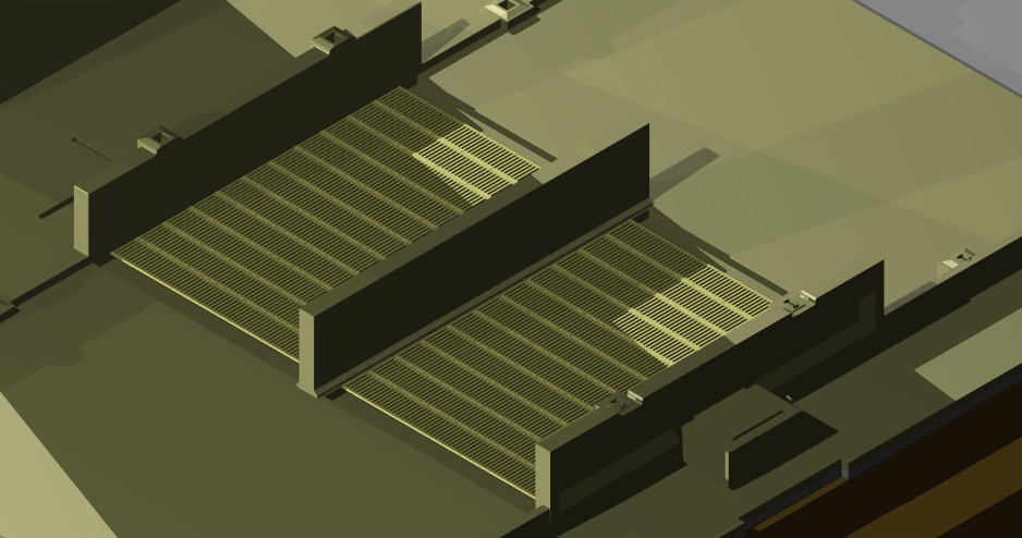
6. The discharge grates are 0.3 mm etched brass, that are placed on a thin section of styrene to level them up with the top of the wagon shed road way. There is a small section on both ends of the grates that will be filled in with slight rounded risers, as per the prototype.
 |
Brass grates added to the model.
|
7. The drainage system is made of of 3D prototyped parts that have been designed to fit in laser cut holes in the base, and glued into place. The joins are then filled and sanded to a smooth finish. The "H" pattern in the drains allows for support beams to be placed into place for the out loading platforms
 |
| Parts for the drains made from Strong and Flexible plastic at Shapeways in the Netherlands |
 |
The drainage system in place on the silo base.
|
 |
| Close up of the drainage parts, note the tabs on the p[arts which fit into the holes in the base. The "H" pattern in the drainage parts, allows for the out loading platform supports to fit into place. |
8. The elevator tower, is made up from various laser cut 1.5 mm acrylic pieces that tab together, the notches at the top of the tower accommodate the silo bin roof sections. While the small holes on the side of the tower top, allow for the conveyor and distribution chutes.
 |
Elevator tower located onto the base.
|
 |
| Elevator tower top, the sloped cut outs on each side are to accommodate the bin roof sections, while vents fit into the front and rear holes with doors and discharge chutes on the sides |
Well that is it for now. more information and photos shortly. Next installment, I will be looking at the other components to fit into the base, as well as the bins and bin roof sections.


No comments:
Post a Comment