Saturday, June 1, 2013

Bins and Bin Roofs

Howdy gang.


     The thing about model silos is ultimately the 3rd dimension-----height------ and Merriwa relates greatly to this dimension. The bins are 104 ft tall or in model terms, 364 mm with the elevator tower being a further 120 mm, giving a total of 484 mm and that sits on a 12 mm base, so from base to top we have a total height of just under 500 mm. From a model point of view this is immense, and if placed in a layout, the layout does need the depth and length to ensure that the silo is not too overpowering. Honestly these things ARE overpowering and that is just a fact. The last trip up to Merriwa, that I was involved with comes to mind, and I remember as we reached the outskirts of Merriwa, over the rolling hills, we were greeted with this fantastic monolith being the S052 Merriwa Silo, like a magnificent welcoming beacon in the near distance, and we then knew that our journey was complete. Big, yes they are big.

     When I first started designing the Merriwa silo model I was pleasantly surprised that the bins measured 31 ft 6 in in total or 110.25 mm. Surprise, surprise, standard sewer pipe measures in at 110 mm in diameter, ----PERFECT----- we have a winner. So it was a simple matter of designing the silo to fit the commercially available conduit.

Elevation view of Merriwa S052 Silo

     The conduit was now cut over size, and each piece was faced on a facing sander, that was set up with an aluminium jig, to ensure that the pieces are a square as possible. then checked in an acrylic jig used like a go-no go jig, many pieces were rejected and reduced to fit the larger bins in the S016 and S024 kits (so they weren't wasted).

The sanding jig that was designed by my son Tim, which allows a lot of adjustment, for various conduit sizes. The jig allows for accurate face sanding of the conduit pieces.
The face sander with 110 mm conduit being machined, This system produces plenty of dust from the PVC conduit and a vacuum and face mask is necessary.

     Now that the conduit was selected, the steel strapping had to be addressed, as these were prominent features of this and other similar silos. The forces involved with loading and unloading the bins continually, puts a massive strain on these concrete bins, and so to reinforce the bins 6'' x 3/4'' steel strapping was placed on all of the bins in the stress areas of the bins, hence they are only located in the middle sections of the bins. There are 16 steel straps, roughly 6 ft apart.
   

      Evergreen 6'' x 1'' HO styrene strip was used to simulate these steel bands. Many packets of this material were needed, (3 bins x 16 pieces, 48 pieces ----10 pieces per pack----LOTS OF THE STUFF). Luckily each piece, was just a tad longer that the bin circumference, which was only required for the lone standing bin as the other two bins are attached to the elevator tower, and the band is not required where they join to the tower.

     Now, one problem to overcome was how to get the strips, in the correct position and square with the model. The first thing, where do we start? This was achieved by using a 5 meter staff to obtain a rough starting point, and measuring the material thickness and the gap between each band, then scale this information to the model.

The staff showing the height of the fist steel band on the silo. The starting point.


     Al Cutmore  (AR Kits) once showed me a method where you can use a vernier gauge as a scribe, to scribe a line in plastic, and that is what I employed on the bins. It is a slow and laborious task, but necessary to achieve a great result. The vernier is 300 mm long and the base of the bin is used as a datum point and the vernier is adjusted and then locked in position and all 3 bins are done at the same time. The scribe line is locate at the base of each strip and the styrene strip is butted up to the scribe line (slight ridge), keeping the styrene in line while running glue between the strip and the bin. micro adjustments were required to ensure that the strips line up. After doing this to three bins, it become very tiring, due to the fact that you need to get it correct the first time. next the bin roof.
The 110 mm conduit with styrene strips glued in place. The markings are for the location of the out loader in number 1 bin

     The bin roofs are an octagonal shape and and made up from layers of 1.5 mm acrylic. Just a note about acrylic/perspex etc. The 1.5 mm acrylic is a cast materiel and as such can vary from one corner of an 810 mm x 460 mm sheet to another. In some cases, it can be anywhere from 1.45 mm up to 1.75 mm. This can present problems with ant tab and hole joints that are used, as the hole is laser cut and is accurate, but the tab that fits into the hole can vary and in some cased requires sanding, so that it fits snugly. Forcing acrylic together when it is too big will result in cracking that can be extremely frustrating.
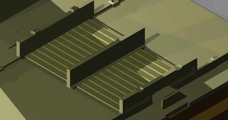
Merriwa Roof Plan showing octagonal roof and conveyor.
The components for 1 roof, the 1.5 mm acrylic is covered with brown protective paper. 
Pegs are used to hold the base and circular pieces together so that glue can be run into the joint. The 6 mm brass tube centres the 2 pieces,  the lamination process makes the base much more rigid.
The sanding block is a simple piece of 9 mm craftwood with sand paper glued to both sides, the uprights required sanding to fit into the tabs on the base.

So back to the roof construction. There are 18 acrylic parts for each roof. The basic octagonal shape, and circular piece slightly smaller that the inside diameter of the conduit. 8 risers, and 8 roof sections, designed to fit snugly together. The pieces are glues together with DCM (Di Chloride Methane), to hold in place, then sanded so that each joint is smooth and then hit with thin fast drying supa glue. The edges of each roof section are sanded extends at an angle slightly and need to be sanded flush with the base pieces, then filled and sanded clean and smooth. There is a 6 mm hole in the middle of the roof which caters for a brass tube that is attached to the top conveyor of the silo. Finally a small piece of acrylic is glued to the base of the roof over the hole as a stop for the brass tube.
The finished  roof ready to have the joints and edges sanded smooth, filled and sanded, ready for cladding, and drilling.

The bin roof sitting on top of the  conduit, the circular section is laser cut to fit with a small amount of movement for adjustment.
     The bins are then clad in corrugated iron, a small styrene drilling jig is used to pivot on the brass tube, and small pilot holes are located to allow the positioning of the roof vents. there are four of these vents on each roof and there are located equally on 4 of the roof sections. Not all bins have the same treatment. the stand alone bin has a stair section as does the bin next to it, which is recessed into the elevator tower. The bin on the other side of the elevator tower is also recessed, and has stairs and an access door leading into the elevator.


The roof showing the recess into the elevator, as well as the stairs going down to a door into the elevator.

The steel work at the top of the  roof is comprehensive, and is a feature of the silo. Access from the roof to the conveyor, is also provided via a ladder.

On the next installment, there will be more on the steel work and how it is modelled, to great effect. as well as the conveyor, and cladding the silo in general. until then, happy modelling.

Saturday, April 27, 2013

 Hi Gang

Well after a long sabbatical, I am back with  the start to finish of the construction of the Merriwa Silo in HO, So lets begin. I have been building silos for a few years now and have developed methods that have proved to be reasonably successful. I always start with a solid base,  as with any building a solid base or foundation is always a good place to start.

The Merriwa S052 Grain Silo is an impressive structure with a height of over 140 feet (490 mm), it needs to be built on a base that also doubles as a base for it's own storage and transport box.

1.     So I start with the base of the silo, measuring 745 mm long x 240 mm wide on 9 mm craft wood  this is secured to a 12 mm sub-base, using 10  T- nuts. The box actually fits on the outside of the 12 mm base and is secured with screws through the sides. Seal the craft wood  with a clear lacquer to stop any chance of moisture infiltration.
Silo Base with 10 T nuts and sub base made from 9 mm and 12 mm Craft wood.
 2.     This particular silo is the result of many hours of work in the design process, and uses many laser cut acrylic parts, brass etchings and 3D prototyped parts and a few components that needed to be scratch built using jigs so as keep them consistent. The acrylic base that is use as a starting point is laser cut from 1.5 mm acrylic with certain holes cut into it so as to locate other components. The base is glued to the craft wood using Selley's Gel Grip adhesive. Placing some weight on the acrylic whilst it is drying will help to stop it from lifting later on.
 The 1.5 mm acrylic base is glued to the 9 mm craft wood using Selleys Gel Grip adhesive. The small holes at the rear, assist in locating the wagon shed foundations.

3.     More 1.5 mm Acrylic pieced are placed onto this piece to build up the base. All the acrylic can be glued using superglue or Di-chloride Methane (use with caution, as it can be dangerous if inhaled). The piece below has holes in it to allow the location of the wagon shed foundations, a centre partition to separate the 2 wagon shed grates and holes for the drainage system. The drainage system in these silos is very important as the lower conveyor and electrical equipment needs to remain dry at all times, and the drains are critical in diverting water away from the silo base.

More acrylic is added to build up the base of the silo.

The small sections of acrylic are bases for the drainage run off., note the small slots between  the bins, that locate the elevator, tower.
 4.     This piece is located and glued in place, and shows the location of the 2 discharge grates in the rear of the silo.The basic pattern of the silo is now becoming more apparent.
Silo base starting to take shape 

5.   The foundations for the  wagon shed frame are next, these were designed so that they accept Special Shapes I and H beams. The outer frames will accept B-3-1x (3/32" x 3/64") beams, whilst the inner frame is made from S-2x (5/64" square brass). The middle partition id simple that a separator or partition for the 2 discharge grates.
The foundations are glued into the laser cut holes in the acrylic parts.

A close up view of the footings with holes in them to accept the I beam and square  brass uprights.


6.     The discharge grates are 0.3 mm etched brass, that are placed on a thin section of styrene to level them up with the top of the wagon shed road way. There is a small section on both ends of the grates that will be filled in with slight rounded risers, as per the prototype.

Brass grates added to the model.


7.    The drainage system is made of of 3D prototyped parts that have been designed to fit in laser cut holes in the base, and glued into place. The joins are then filled and sanded to a smooth finish. The "H" pattern in the drains allows for support beams to be placed into place for the out loading platforms
Parts for the drains made from Strong and Flexible plastic at Shapeways in the Netherlands

The drainage system in place on the silo base.


Close up of the drainage parts, note the tabs on the p[arts which fit into the holes in the base. The "H" pattern in the drainage parts, allows for the out loading platform supports to fit into place.

8.   The elevator tower, is made up from various laser cut 1.5 mm acrylic pieces that tab together, the notches at the top of the tower accommodate the silo bin roof sections. While the small holes on the side of the tower top, allow for the conveyor and distribution chutes.
Elevator tower located onto the base.

Elevator tower top, the sloped cut outs on each side are to accommodate the bin roof sections, while vents fit into the front and rear holes with doors and discharge chutes on the sides

Well that is it for now. more information and photos shortly. Next installment, I will be looking at the other components to fit into the base, as well as the bins and bin roof sections.

Monday, January 24, 2011

Step 2 Planning the Model

Silo bin roof showing conveyor, bin roof and silo roof vents.

Top conveyor with electrical box, motor/gearbox drive, walkway and handrails.
Conveyor with walkway, conveyor cover sections, ladder and walkway down to silo bin roofs.
Short end of walkway with grain feed chute to bin No1, note that the corrugated iron has 3in corrugations which allows the measurement of other parts such as the door width and vent width.
Outloader type on centre of elevator, with lighting
Outloader on No 1 Bin
400 tonne outloader on bins 2 and 3
Front of silo showing corrugated iron, outside of hopper bin, silo rings and centre outloader.
Rear view of silo elevator, with louvred vents and silo rings and top of wagon shed.

Vent for base of silo left hand end.
Vent for base of silo right hand end, concrete sections to be prototyped.
Partitions and wagon shed support footings with grate.
Partitions and wagon shed support foundations, with grate.


The first question that comes to mind when planning to build a large structure such as a silo, is , what is available commercially. By this I mean what size are the silo bins, and what commercial conduit is readily available to suit. Luckily the bin diameter for the Merriwa S052 Silo worked out to be 30ft with a wall thickness of 7.5 in. The total dimension being 31ft 3in, in HO scale, this relates to 109.375mm. Well blow me down if 100mm sewer conduit is 110mm o/s diameter, how lucky was I? So the plans will need to be adjusted to suit the conduit, and everything that comes in contact with the conduit is varied to suit. This will mean very little change from the plans.

Now that that we have the bins covered, we need to know the height of the silo, and luckily for me, I was able to get access to a few plans which give the levels from the base to various levels. This ensured that the silo looks correct and the aspect is kept to the prototype. There will, no doubt, be certain items that may to be adjusted to suit, but at the end of the day, if anyone wants to put a vernier gauge over the silo just tell them to nick off. I have a simple philosophy, with model building: “while the model should be accurate to the prototype, more importantly it has to look right”.

I needed to work out the materials that certain parts of the silo need to be made from. From the base all the way through to the roof of the elevator. So the logical starting point is the base or foundation. I always build models on a craftwood sub-base, using T-nuts to screw it into a full base that forms the base of the storage box that the model is delivered in.

The actual base of the silo is naturally set up from rail height and the base will be built up using laser cut acrylic that has had holes, laser cut to suit the inclusion of all the parts that build up from the base. The partitions in the wagon shed will all be prototyped from Shapeways in the Netherlands, as will the footings for all the wagon shed supports. These can include the holes for the wagon shed supports and the nut/bolt detail if required. The footings can then be located directly into the holes in the base, which makes the model more accurate in assembly. The grates in the wagon shed are photo etched brass, to suit the holes that they fit into.

The internals of the wagon shed are scratch built over paper plans using special shapes brass profiles and soldered together. Small angle can be substituted with small square section to allow easier construction and making the silo cheaper to construct. Corrugated iron is used to clad both the wagon shed and the workhouse and elevator. I prefer to use Campbell’s Corrugated Aluminium. This material comes in packets in sizes from 4 scale feet to 12 scale feet. I suggest that the most economical packets to use are the 12 feet ones. You can cut smaller lengths from the longer sections.

There are 18 louvered vents, and various doors that will need to be prototyped in the finest material possible, and designed to simply press into the holes after the corrugated aluminium has been fitted. The shed in the wagon shed is laser cut, tabbed, glued and clad, with prototyped doors windows and vent.

Possible the hardest job on this particular silo will be the locating of the rings on the bins. Locating the starting point was as simple as measuring from the base, and then testing what looks correct when doing the drawings. The rings can be Evergreen styrene strips (6in - scale). An important part of any silo are the drains, and in this silo the drainage surrounds the entire silo, and can easily be made from laser cut acrylic and tabbed into the acrylic base. Other parts that will be prototyped and scratch built include the vents at both ends of the silo and the various outloading chutes .

The elevator and bin roofs will be made in laser cut acrylic, which can then be clad in aluminium. The hopper bin will be scratch built from brass section. The bin roofs will be built up from acrylic sections that are tabbed and glued so that they fit the 100mm conduit neatly. Pipes will be located into the centre of the roof builds so that the top conveyor and walkway can be located easily and accurately. I believe that models with the external parts needing to be attached can be plugged into the base structure, allowing painting off the model, and then touch up to blend the part to the model when installed.

The conveyor and walkway will need to be scratch built. The closed conveyor can be prototyped in sections and glued together. The walkway will be etched and the handrail supports are all scratch built with jigs to keep them uniform. The roof vents will be prototyped, and then have etched brass detail added.

So, as you can gather, there are many parts to the construction of a silo, and if you plan it correctly the construction method will flow easily. Of course, the whole planning method revolves around 3D drawings of the sections, which then allow the correct fitting of parts , and sub parts, this method of 3D CAD construction is time consuming but saves time overall, in that you only need to do it once, and correct any mistakes as you go. If you use the trial and error method in the actual building process, it would be more costly at the end of the project. The other advantage to using CAD , is that all the prototyped parts need to be drawn in 3D anyway.

So the next posting, we will discuss the foundations and acrylic base, until then BYE for now.

Tuesday, December 28, 2010

Introduction to this project

Front view of Merriwa S052 Concrete Silo, with D150 in the background
Elevation view of Merriwa S052 Concrete Silo

Plan view of base of silo foundations with dimensions.


Hi Gang
I have had a recent
thought that while I have to construct 5 by Merriwa S052 Grain Silos in HO, I might as well do it through a blog, and at the same time show some of the construction methods, that I use and get feedback from other modellers as to their thoughts on the subject.

In the next few months it is hoped that this blog will show; methods of construction, tools required, materials used, skills learnt in the process, links to suppliers, computer programs used to achieve certain results and plenty of patience.


This project started a few years back when Ian Millard showed me a few photos of the Merriwa So52 Silo, and suggested that I might be able to build one for him. The idea appealed to me, and so I set about researching the information. Now if any of you have researched any information you know that it can be frustrating and very involved.

I already had basic knowledge about the silo, regarding its date of construction and silo type. What I didn't have was a plan and and detailed photos. This basic plan information has been
sourced in the mean time and backs up the information that I have sourced on site, on my original site visit a few years back. I have recently travelled back to the site 2 weeks age to
finalise some measurements and working photos that are necessary to get the detail for this project.

STEP 1. Go to the site with camera and tape measure (and other things).

With the growth of hi meg digital cameras, you have the ability to take hi resolution
photos that not only allow you to see the detail better, but also allow you to zoom further into the photo and still have a clear view of the smaller detail components. I have a Panasonic Lumix DMC FZ28 with 10 megapixels and 18 x optical zoom. I have a 2 gig SD card, which will hold "LOTS" (Technical term many many photos) of photos even when the camera is set at 9 meg per photo. I like the larger setting as it allows me to zoom into the photo without loosing detail. very handy when you cannot get close to the detail.

So armed with the my son Tim, the camera, my note pad, pencil, pen, another pen, expendable staff (measuring stick) 8m/26ft tape measure, new ladder (as seen on TV), we set off for Merriwa at 4.30am on a grey Sunday morning from Picton (using the Tom Tom, up the M5, M7, Putty Road, Golden Highway to Merriwa, a trip of around 4 1/2 hours. Breakfast at Denman then a short hop to Merriwa, when the silo greets you as it slowly appears, from the surrounding valleys.

I have a great many photos of the silos from a past trip, but unfortunately they were of a much lower resolution, and the detail was not ideal. There was also some of the finer measurements that made no sense and needed clarity.

I processed the photos on site by removing the SD card from the camera and placing it in my laptop and viewing the photos and seeing if any more detail was required (I love technology - it really is instant). Once happy with what information had been gained, it was time for another run down the Putty Road (Now there is a fun trip---Not)

Drawing up the plans.

This step fairly involved, and can be broken down into sub steps to make it a little clearer.
I like to draw plans in 12 inches to the foot, then I can reduce them to whatever scale that I wish to work in. This process has served me well over the years and "works for me". So if I was to do the model in HO or 7mm, I can scale down the drawings and just adjust them for available material sizes.

To do the drawings I use Turbo CAD V16.2 Platinum, however earlier versions of Turbo CAD are available on the net at a very reasonable price, as are training videos to make the learning curve much easier to cope with. Word of warning, to use these CAD programs involves a great deal of time to understand the program and it can be a very steep learning curve, but the time taken is well worth while, so do persist. I also use Corel Draw to draw etches and again this program has a great video tutorial that can be purchased online. For 3D prototyping you will need a good 3 D program so that you save any of you 3D files as STL files to export to companies such as Shapeways or Rapid Prototyping.


NEXT WEEK ---Step 2 Planning the Model